Features
DSO 068 DIY kit uses through-hole components as much as it can. This makes the scope unique among peers. With through-hole components the kit eases off the requirement of assembly skills and at the same time
allows deeper user involvement. Most importantly it brings in the freedom for users to test, modify, experiment, and even design their own projects. And this means more fun!
More over, DSO 068 is not just a kit for training but also a practical tool for everyday use. It was designed on the base of DSO 062 kit and comprises many enhancements in hardware and firmware. Major
improvements include:
Higher sensitivity (10mV/div vs 100mV/div)
Wider analog bandwidth (3MHz vs 1MHz)
Larger capture buffer (1024 points vs 256 points)
Variable trigger position (1% - 100%) with indicator
Test signal generator with variable frequency and amplitude
USB connection
Work as USB scope (with
jyeLab) and data logger (8 channels, 10-bit resolution)
Higher sensitivity (0.2Vpp vs 3Vpp) in built-in frequecy meter
Battery/USB powered
Fully enclosured
See chart:
DSO068 vs DSO062.
Operations of DSO 068 are even easier thanks to silicone pushbuttons and rotary encoder. Parameter setting is simply, straightforward, and quick. Mode switch and
utilities are driven by menu. Absolutely no complicate navigation.
This kit is particularly suitable for educational use. It is a great tool for college students.
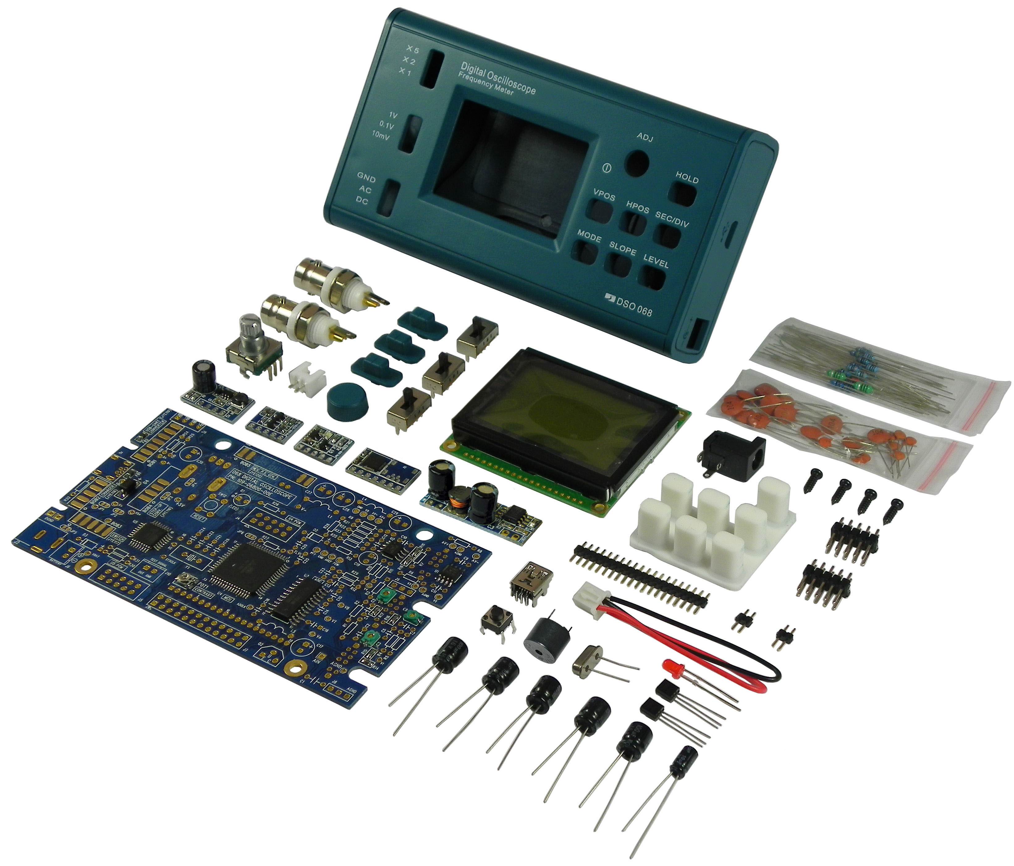
Contents
The DSO 068 Kit consists of the following major parts:
( 1 ) Main circuit board with pre-soldered ICs and a few SMD parts. Board is pre-tested and MCUs on board are pre-programmed.
( 1 ) 128 X 64 graphic dot-matrix LCD module.
( 1 ) Step-up voltage converter board (JYE116). It boosts battery voltage to 5V from as low as 2V.
( 1 ) Voltage inverter board (JYE120). It generates -5V form +5V with current capacity up to 200mA.
( 1 ) On/Off switch board (JYE117). This is the power switch of instrument. [optional]
( 1 ) Li-ion battery charger board (JYE118). It includes the USB/Battery power switch circuit. [optional]
( 1 ) USB-Uart converter board (JYE119). This bridges the scope to USB host. [optional]
( 1 ) Professional 20MHz probe with selectable 1X/10X attenuation.
( 1 ) Enclosure set including stand, switch caps, etc.
All through-hole components, mechanical parts, and accessaries.
Shipment of kit also includes color-printed Assembly Guide and User Manual. All other documents can be downloaded at this page. It is suggested that users also download
the softcopies of the accompanying documents for enlargement to have better viewing on screen.
NOTE: Battery is not included in standard product configuration and need to purchase separately. Shipments containing battery could incur higher shipping cost
and longer delay due to restrictions of shipping agents.
Source codes of student version firmware are also provided for downloading. They are simplified from full version to help users to understand how the oscilloscope works. The sampling rate
of student version is limited to 500Sa/s - 100KSa/s with no other features.
Ordering Info
Sku Number
Contents
06804K
One DSO 068 DIY Kit (full version) (battery not included)
One BNC probe (20MHz, 1x and 10x switchable)
[photo]
Users Manual (English)
Assembly Guide (English)
Product Documents and firmwares:
Supporting Documents and Tools:
Specification
Vertical
Number of Channel: 1
Analog Bandwidth: 0 - 3MHz
Sensitivity: 10mV/Div -- 5V/Div
Resolution: 8-bit
Input Impedance: 1M ohm
Maximum Input voltage: 50Vpk (for 1X probe) and 400Vpk (for 10X probe)
Coupling: DC, AC, GND
Horizontal
Max Real-time Sampling Rate: 2MSps
Max Equivalent-Time Sampling Rate: 20MSps
Timebase: 0.5us/Div - 10m(minute)/Div
Record Length: 256, 512, and 1024 variable
Run/Hold Modes: one button switchable
Trigger
Trigger Modes: Auto, Normal, Single
Trigger Types: Rising/falling edge
Trigger Position: 0% - 100% of capture buffer adjustable
Trig Point Indicator: Yes
Test Signal Generator
Frequency adjustable from 1Hz - 100KHz (41 frequencies)
Amplitude adjustable among 0.3V, 1V, 3V, and 5V
Other Features
Save captured waveform to EEPROM and recall after power outage
Upload screen display as bitmap file
Upload waveform as CSV file
USB connection for data transfer and firmware upgrade
Rotary encoder for quick parameter setting
Display
2-inch 128 X 64 black-and-white dot-matrix LCD
Backlight ON/OFF control
Contrast adjustable
Power Supply
3.7V Li-ion battery/USB
Supply Current: 300mA @ 3.7V(LCD backlight ON, typical).
Built-in charger
Physical
Dimension: 140mm X 70mm X 30mm
Weight: 120 gram (not including battery and probe)